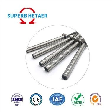
Analysis of Common Failures of Industrial Thermocouple Measurement Devices
Leave a message
The simple structure of the thermocouple determines its extremely plastic application shape. It can be processed into different thicknesses, lengths, single or double (usually double thermocouples are used, one as a spare) according to needs. Some thermocouples, such as armored cable thermocouples, can be bent and twisted at the head to meet the different installation shape requirements of the on-site equipment when used.
*The measurement principle of the thermocouple is the thermoelectric effect. The biggest difference between it and other sensors is that it can generate signals without adding any excitation power supply. However, it generates extremely weak electrical signals, usually only tens of millivolts. In order to prevent signal distortion, it has high requirements for the transmission of thermoelectric potential: first, a dedicated cable (called compensation cable) must be used, and the compensation cables of different types of thermocouples are also different (E type with nickel-chromium-copper wire, K type with copper-constantan wire). Secondly, the shielding requirements for interference signals are high, and the cables usually use double-layer shielding.
Cold end compensation
The cold end compensation function of thermocouples has been widely moved into DCS. Taking the INFI-90 control system as an example, all I/O cabinets are placed in an electronic room with a constant ambient temperature (generally 18℃~21℃). In this way, when performing cold end temperature compensation in the I/O terminal cabinet, a high-precision measurement value can be obtained. When the cold end temperature of the thermocouple is zero degrees Celsius (referred to as t0), the compensation bridge R1= R2= R3= RF(t0), the bridge is balanced, the compensation voltage Uba=0, and the total potential of the temperature measurement circuit is EAB(t,t0). When the cold end temperature of the thermocouple changes, such as rising to t1, although the thermoelectric potential of the thermocouple decreases, due to the increase in the RF value of the thermistor, the compensation bridge will have a Uba voltage output, and the total potential of the temperature measurement circuit is EAB(t,t1)+Uba. Only by choosing the working current value of the compensation bridge, the compensation voltage Uba can be exactly the part of the thermoelectric potential EAB (t, t1) that is reduced due to the rise in the cold end temperature, so that the total potential EAB (t, t0) of the temperature measurement circuit remains stable.
The thermoelectric potential EAB (t, t0) after the above compensation enters the signal isolator, where it is isolated and transmitted to convert the millivolt signal linearly into a 1~5 volt signal (calculated based on 900℃ as the full scale) and then input into the I/O card. The analog/digital conversion is performed in the I/O card and finally sent to the controller card for calculation and control.
Software processing and control
The temperature signal entering the DCS controller card is a digital signal (when monitored from the engineer's workstation, it still displays the millivolt value), which is linearly related to the input millivolt voltage value, so to convert it into a temperature signal, it is also necessary to perform interpolation calculation in a list.
At the same time, in order to ensure the reliability of the entire measurement system, multiple measuring points are installed on-site for each main and important temperature measurement parameter in the control logic. For example, for the outlet temperature of the superheater, dual measuring point input is redundant measuring point input or three measuring point input, and the corresponding control logic adopts two-choice or three-choice.
According to the law of heat transfer, the speed of heat transfer depends on the thermal resistance of the heat transfer body. Therefore, the response of any temperature measurement device to the temperature field measurement is much slower than that of the flow, liquid level, and pressure signal. Besides, there is usually a protective sleeve outside the thermocouple element. Therefore, its response to temperature changes is not a step characteristic but close to an inertial characteristic. For this reason, some leading components should be added to the main control PID of the temperature control on site to prevent the temperature of the controlled object from being over-adjusted.
Common faults and analysis
The common faults of thermocouples are mainly manifested as follows:
a. The compensation wire of the thermocouple is connected in reverse. This is mainly a problem that occurs during infrastructure construction. It is caused by the temporary carelessness of the person in charge of wiring and is a labor factor. When a thermocouple appears
b. The insulation layer of the thermocouple's compensation wire is worn out, causing the signal loop to be grounded. This is mainly because the compensation wire is hard and is not installed flat in the junction box. When troubleshooting, the junction box cover is repeatedly screwed and the compensation wire is worn out. This kind of fault is reflected in the temperature indication on the operator's control station, which is generally small.
c. The wiring terminal in the junction box has poor contact. Because the compensation wire and the thermocouple wire are both hard, it is difficult to tighten the wiring during on-site inspection. Sometimes the wire is tightened at the beginning, but it becomes loose again after a while as the wire deforms. This kind of fault is reflected in the temperature indication on the operator's control station as no indication or the indication value exceeds the range.
d. Compensation resistance failure. This kind of fault is manifested as a slow rise or fall in the temperature indication value after the thermocouple is connected.
e. The failure rate of the thermocouple measuring the flue at the tail of the boiler is high. During the shutdown inspection, the thermocouple was removed and it was found that the head of the thermocouple, including the sheath tube, was severely worn after being washed by flue gas. After the sheath tube was changed to wear-resistant steel material, this kind of fault hidden danger was eliminated.
f. The signal protection system DCS cabinet is poorly grounded. This kind of fault can easily cause electric charge to accumulate on the signal line, causing signal drift or fluctuation. Because the fault point of this problem is difficult to find out, the usual treatment method is to disconnect the signal line and discharge it to the ground.
g. The temperature input signal fails after passing through the disconnector, which is reflected in the abnormal temperature value signal on the operator control station. It is normal after replacing the disconnector.
The above are common problems encountered during inspections, but when looking for these faults, it is recommended to first use a multimeter to measure the input voltage value on the I/O terminal cabinet of the DCS, so that you can quickly determine whether it is a problem at the on-site measurement end or a problem in the DCS department. For multi-point inputs, you can also compare it with several other thermocouple signals. If you can't determine it, untie the wires and measure its resistance value. Usually, the resistance value of a thermocouple is about 100Ω.
Thermal resistor measurement device
The application rate of temperature measurement devices using thermal resistors as temperature measuring elements in thermal power plants is second only to thermocouples. Ordinary domestic thermal resistors are about 1,000 yuan each, which is more expensive than thermocouples, but have better characteristics at high temperatures and higher measurement accuracy than thermocouples. They are mainly used to detect measurement points with temperatures below 200°C. At present, it is used to measure the temperature of generator coils and fans and coal mills.